

In many industries, such as power generation, inspection is a required element of the management of plant structural integrity. Early recognition of structural defects means steps can be taken to safely rectify plant issues whilst maximising plant availability. It is common to examine plants through life – at the conclusion of manufacture and then at intervals during a plant’s operating lifetime. This latter inspection type is known as In Service Inspection (ISI) and generally involves powering down the plant, allowing personnel access to plant items to apply the required inspections.
As a potential alternative approach to conventional ISI, a trial based upon the use of permanently installed, high temperature ultrasonic sensors arranged in a relatively sparse array on the component to be inspected was conducted. In this approach, ultrasonic data can be collected at any point during plant operation, without interrupting operations.
The system, from KANDE, is known as PUMA (Permanently installed Ultrasonic Monitoring Arrays). Response data can be analysed effectively using several approaches, including differencing of historic and current echo data and the total focusing method (TFM).
While the technology discussed here has applicability across a range of industrial sectors, it is primarily targeted at ISI of power generation plants, in general, and light water nuclear power generation in particular.
The primary concern associated with suspending plant operation during ISI, is the reduction in plant availability. Other potential benefits of monitoring compared to conventional ISI are:
- Early warning of defect initiation
- Reduction of exposure of personnel to ionising radiation
- Inspection whilst the component is under operating pressure potentially making defects more readily detectable
- Reduction in thermal cycling associated with outages for inspection can be reduced
The project brought together specialists in ultrasonic transduction and monitoring technology from KANDE and mathematical modelling specialists from the University of Liverpool (UoL) Department of Mathematical Sciences and was funded by the UK Government’s Game Changer scheme.
Sensor and array design
KANDE supplied the sensors used in this application, which are 0°, relatively small and low profile, suitable for permanent installation below thermal lagging. The transducer crystal size is a key design parameter as divergent beams reduce the need for a closely spaced array at the expense of reduced beam intensity and possible reduction in signal to noise ratio (SNR).
Owing to logistic issues associated with the support grant, it was necessary to obtain results from the study within a three-month period which meant procurement, fitting, design, instrumentation and soak-test setup needed to be completed within one month of the grant award. In practice, the soak-test ran on for six weeks after the conclusion of the project. The array has n elements and is used by pulsing on one element and receiving on all n elements. The transmitter element is progressed through the array and for each pulsed element, all elements receive. In this way a total of n2 signals are collected in one data collection operation. In this trial, n=28.
To be effective in detecting, sizing and characterising any defects within the inspection volume, ultrasonic beams from the sensors in the array need to:
- Insonify the full inspection volume
- Provide sufficient beam overlap that a credible defect could scatter signals to multiple member elements of the array
- Generate signals from the defect with sufficient signal to noise to enable defect detection and sizing
- Produce propagation paths from the array elements to points in the inspection volume that are sufficiently diverse to enable location with minimal ambiguity.
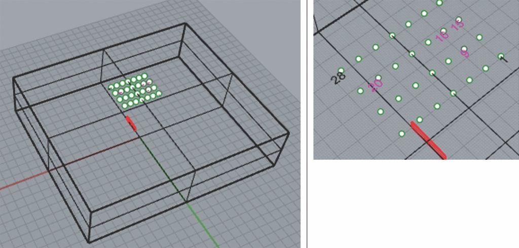
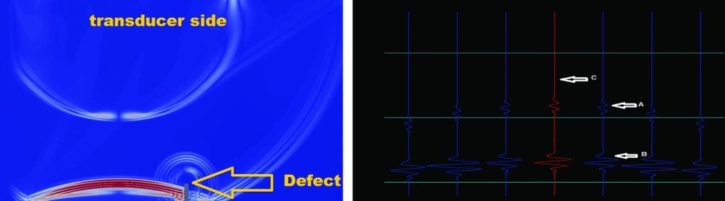
A first draft array design was produced manually on the basis of physical reasoning and simple beam spread and timing considerations. This preliminary design (see Figure 1) was then tested and refined on the basis of finite element (FE) modelling using Pogo software. UoL members of the project used FE modelling to give insight into the monitoring arrangement considering 2-dimensional and 3-dimensional modelling exercises. Calculations were performed to tailor the draft design. As Pogo can output time series data (see Figure 2: Right pane), it was possible to test the monitoring system analysis tools for the particular application, prior to sensors being installed.
The experimental study
The study was intended to replicate conditions which might be encountered in pressurised water reactor (PWR) nuclear power plant (NPP) applications by using typical pressure vessel steel, plant operating temperatures, and seeking defects of a type and size similar to those sought in typical NPP inspections. The sample used in the study was a flat, parallel-sided, forged SA508 ferritic specimen which is both similar acoustically to other ferritic pressure vessel steels and commonly used as a pressure boundary material in NPP. This material would be fine grained, homogeneous and isotropic.
The synthetic defect introduced into the component was a slot ~1.0mm wide, 20mm long and 5mm deep. While critical defect sizes vary depending upon the plant and component, this is similar to defects commonly sought in pressure vessel inspections. The specimen was 52mm thick and 28 elements were fitted to the sample. They were arranged in a 4 x 7 (XY) array. The array was symmetrically located over the defect such that the fourth Y element in the array column was located directly over the synthetic defect. In the trial case the array spacing was ~10mm. Strong signals from the defect were discernible across the entire monitoring array leading to the conclusion that the array density could be decreased. Electrical connections were made onto the sensors and then to monitoring equipment. On fitting the sensors, an installation tool broke which limited fitting quality for one of the sensors. The result was reduced sensitivity and increased noise on that channel (marked by a pink circle in Figure 3).
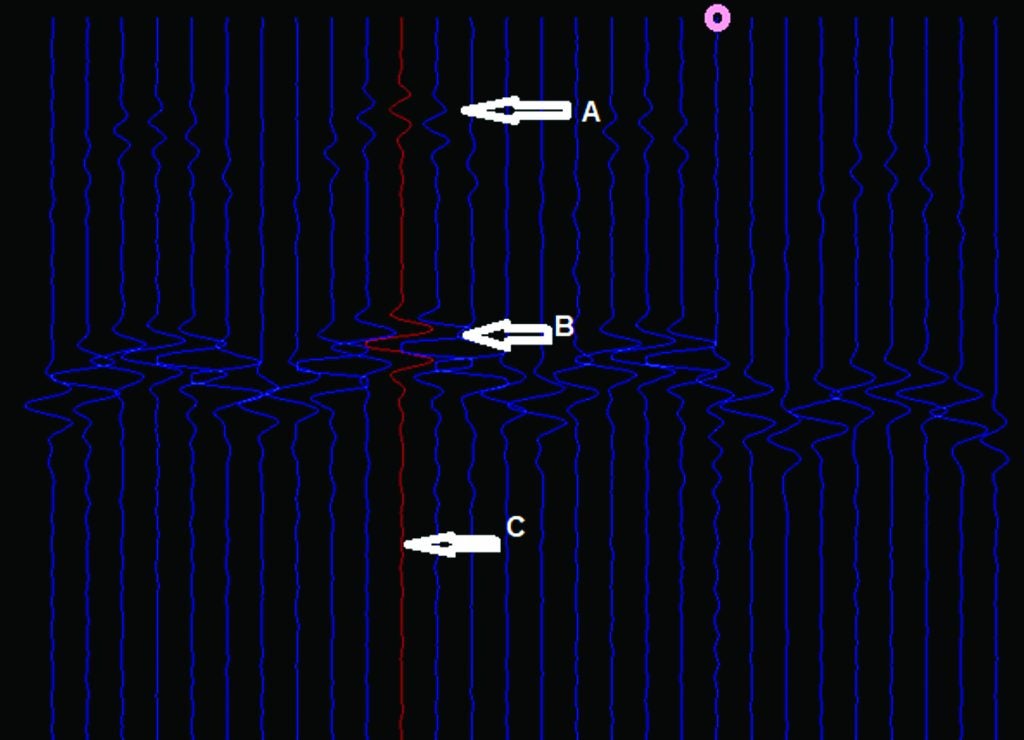
The variation in sensitivity could be measured by examining the backwall echo in pulse echo operation across the array and was better than 4dB across the set (excluding the damaged element). During the soak-test, the sensitivity of each element either stayed the same or slightly improved. System noise also remained constant. Throughout the test, signals due to the defect were clearly discernible in the data. These signals were constant and processing returned the same defect size and location at setup, during trials at elevated temperature and post-trial.
The PUMA monitoring system comprises inexpensive components which means that the cost of equipment tied-up during monitoring is not excessive. The current system accumulates response data at a rate of about 10 elements per second including repeat firing for averaging purposes. Data collection rates could be increased, but there is no particular merit in high data rates as the time to acquire data is virtually unlimited during plant operation. Scans can be repeated as often as desired and repeat data are automatically compared by the monitoring software over the collection period to check for sensor deterioration or initiation or growth of defects. Differencing of historic and current data means small changes associated with sensor deterioration, or defect growth can be recognised and that a data storage regime can be selected to keep stored, important data without excessive data storage. Data are regularly uploaded to the Cloud for remote analysis and storage. Note too that this facility makes the process available to update system digital twins.
Trial results and future work
During the soak-test, experimental data were collected using the ultrasonic PUMA monitoring system. Defect signals were clearly resolved throughout the trial. With
a modification of the TFM applied to data it was also observed that the known defect size was well matched to the TFM result.
Comparison of experimental results obtained prior to heating, during and after the soak-test showed no significant change in array performance and that throughout, the defect could be clearly discerned in the data before, during and after the soak-test with no significant change in signal to noise ratio. As stated, during the trial no significant deterioration could be identified in the performance of any of the elements.
Experimental and modelled response signals were also compared. Significant features – timing, pulse shape and amplitude data were well matched between the experiment and model predictions demonstrating that FE could be used as a design tool for array configuration.
Once data were collected, various analyses could be performed. TFM-like processing of one entire collection set of 28 x 28 = 784 waveforms matched to a target mesh containing the defect. The TFM peak was located close to (within 1mm) of the buried edge of the synthetic defect.
In a full application, we would also suggest use of differencing tools which look at past and present data and flag differences.
The project team will continue to investigate applications of PUMA technology in areas including:
- More complex component forms
- Anisotropic metals applications, such as dissimilar metal welds
- Different defect types such as stress corrosion cracking
- Further reduction in array density which has been shown to be feasible
The Permanently installed Ultrasonic Monitoring Array (PUMA) high temperature monitoring has been successfully demonstrated to operate for extended periods at temperatures consistent with a water cooled nuclear power plant. This demonstration included revealing constant sensitivity of transducers during the trials with no faults introduced by operation in the defined temperature range from ambient to 370°C with the bulk of the trial at 320-330°C. The trial duration was in excess of three months. The project also demonstrated the capability for detecting and sizing a synthetic defect throughout the extended trial with no loss or reduction in capability as well as the applicability of KANDE’s monitoring tools and software to the task of detecting and sizing synthetic defects.
Acknowledgements
This application of monitoring technology was funded by the UK government Game Changer scheme. The authors wish to express their gratitude for that funding. The project also made use of Imperial College’s Pogo FE modelling tool. The authors wish to thank Dr Peter Huthwaite and Professor Mike Lowe for access to Pogo. Jacobs MID department made a piece of SA508 available to the project which was formed into the test specimen used in this project. Again, the authors wish to express gratitude for this.
Authors: Prof Will Daniels, Dr Ian Atkinson and Dr Chris Bugg of KANDE International Ltd together with Prof Daniel Colquitt and Dr Stewart Haslinger from the Department of Mathematical Sciences at the University of Liverpool (UoL)