
Small Modular Reactors (SMRs) are newer generation reactors designed to generate electric power typically from 20 MWe up to 300 MWe, whose components and systems can be shop fabricated and then transported as modules to the sites for installation. Most of the SMR designs adopt advanced or even inherent safety features and are deployable either as a single or multi-module plant. SMR design is characterised by higher modularisation, simplification and factory-based construction, which maximises reduction of construction and erection cost, and the construction period. Economic gains on account of the reduction of volume of on-site work and shorter deployment times are important consideration for adaptation of SMRs. The key driving forces of SMR development are power generation for a wider range of applications, enhanced safety performance, and possibility to offer better economic affordability in comparison with large reactors. SMRs deployable in the near term will have safety performance comparable or better to that of advanced reactor designs.
Modern Russian SMRs based on pressurised water reactors are used in nuclear shipping industry. The latest marine reactor now in operation is the RITM-200 which is an evolutionary pressurised water reactor developed for universal nuclear icebreakers project 22220 based on the design and operating experiences of fleets of icebreakers with more than 400 reactor-years of operation. Eight RITM-200 reactors have been installed in the icebreaker vessels ‘Arktika’, ‘Sibir’, ‘Ural’ and ‘Yakutia’.
The SMR-type RITM incorporates all the best features from its predecessors, the OK-150, OK-900, KLT 40 series reactors used in previous generations of Russian nuclear icebreakers and the cargo ship ‘Sevmorput’ which has been operating for more than 20 years. This design is now being amended for use in land-based applications.
Developing a design for land-based applications
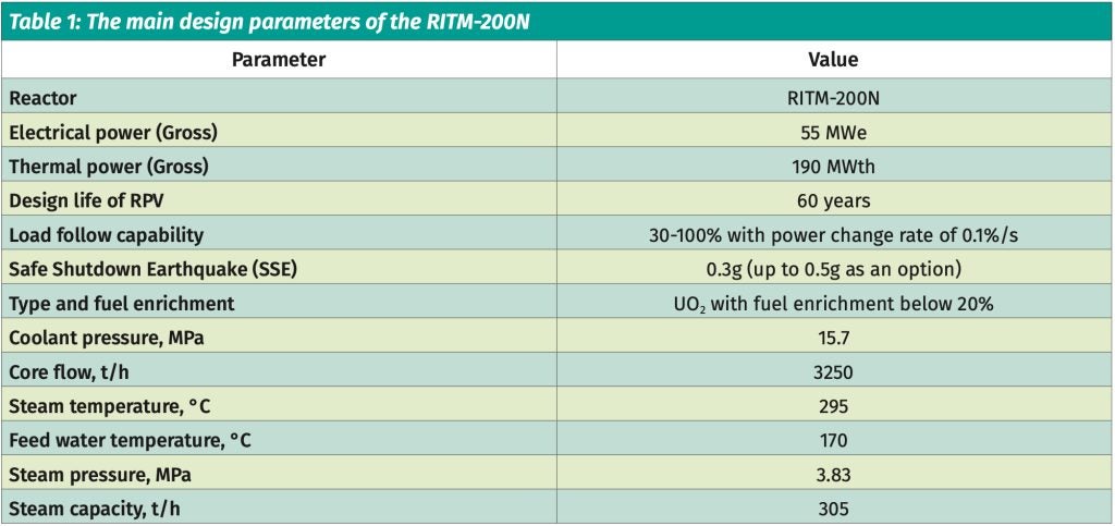
The RITM-200N is the latest development in Generation III+ SMR based on marine PWR technology for land-based applications and has been developed from RITM type plants. It is designed with improved safety, flexibility and a low carbon footprint. It is also comparable with other small capacity reactors on economic parameters. Compared with large PWRs, the RITM-200 has a number of advantages such as higher inherent safety, lower frequency of large radioactivity releases, longer post-accident autonomy without operator intervention, smaller environmental impact, lower site restrictions, shorter construction period and smaller financing requirements, as well as lower financial risk. The main features of this reactor are: use of reference technologies of marine reactors, compact primary system, modular design and fabrication, redundant and diverse safety features – both active and passive – which ensures reactor core safety and extremely low risk of a large radioactivity release.

The parameters of the primary circuit use the proven technical solutions implemented in the nuclear ship building industry (NSSS equipment and its components including the gas pressuriser system) to ensure a high level of reliability of the reactor plant. The choice of the integral layout of the main equipment, the composition and structure of the safety systems and normal operating systems important to safety, make it possible to significantly increase the safety level of the reactor plant. The design solutions of the integrated reactor have also undergone computational, analytical and experimental design verification while individual structural components of the reactor, such as the cover and pipework, are of proven design. The core of the RITM-200N reactor plant consists of cassettes that are analogues of the cassettes currently used in the cores of the RITM-200 and KLT-40S icebreakers.
The main equipment of the reactor (reactor coolant pump, steam generator, control system drives) including the reactor and process solutions adopted in the RITM-200N have been tested during many years of operation and ensure the required reliability and safety characteristics. The cooling system through the process condenser and other systems important to safety of the reactor plant are mainly of a traditional design and have been tested in real operating conditions on nuclear icebreakers.
A self-sustaining ammonia water-chemistry regime and a cleaning system with an ion exchange filter which have been used in ice-breakers, have been adopted for the primary circuit. The water-chemistry regime of the secondary circuit and the intermediate cooling circuit has been developed based on many years of operational experience within the transport shipping industry.
The technological operations for maintenance of the reactor plant are traditional in many respects. The operations of core refueling and replacement of steam generator cassettes (due to the integrated design of the reactor) are similar to those implemented in RITM-200 icebreakers.
The reactor building, reactor annex buildings, special buildings, including the fresh fuel building, are made of monolithic non-pre-stressed reinforced concrete, as well
as steel structures in the turbine building that meet the requirements of reliability, durability, strength, stability and remain geometrically unchanged.
Main reactor characteristics
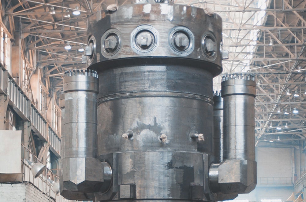
The integral configuration of the RITM-200 reactor, where steam generators are placed inside the reactor pressure vessel, allows the reactor systems and containment to be more compact as compared to the KLT-40S. The RITM-200 reactor design also allowed the electrical output to be increased by 40%, the dimensions to be reduced by 45% and the weight by 35% in comparison with the KLT-40S design.
This integral design of the RITM-200N plant envisages core and steam generators (SG) inside a single vessel. As shown below (right), the reactor coolant pumps (RCP) are welded directly on to the reactor pressure vessel (RPV) which excludes any piping in the reactor coolant system (RCS). This approach significantly improves safety by excluding any loss of coolant accident (LOCA) scenarios within the RCS. The primary circuit includes the integral reactor, pressuriser system, and purification and cooling system.
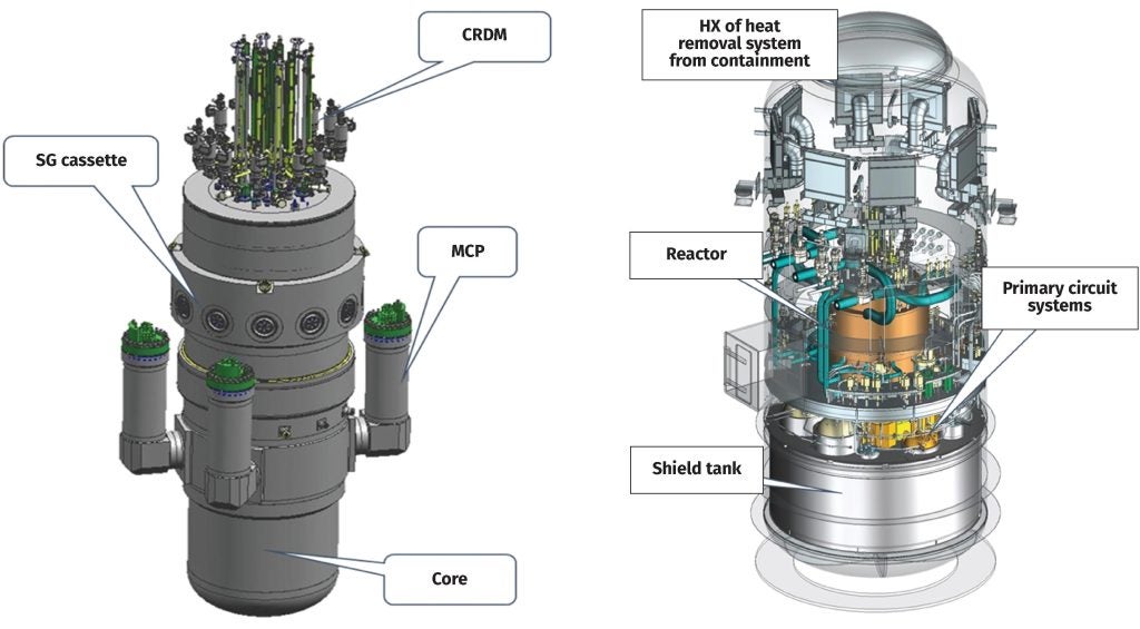
The RITM-200N reactor coolant system is based on forced circulation of the primary circuit separated into four loops with reactor coolant pumps (RCPs) installed in the cold leg of each loop. Each loop consists of three cassettes (twelve in total) with separate feed water manifolds and a common steam manifold. The configuration of the cassettes make it possible to install them inside the reactor vessel for a compact design. Sensors are provided to monitor the temperature of the coolant at the entrance to the core, at the exit from the core, and at the outlet of the fuel assemblies.
The RITM-200 reactor core consists of low enriched (less than 20%) fuel assemblies, similar to those used in the KLT-40S, and thus meet international non-proliferation requirements. Cermet fuel consists of ceramic fuel particles of uranium dioxide (UO2) embedded in aluminum-silicon alloy (silumin). Compared to the KLT-40S, this core has a longer refueling cycle.
The main design features to enhance the fuel reliability of the RITM-200N are as follows:
- High thermal conductivity decreases the temperature inside the fuel columns and reduces the probability of cracking. Cermet fuel is also more tolerant to swelling during its long retention period in the core.
- The fuel rod cladding is made of corrosion-resistant alloy. It is more resistant to corrosion in comparison with zirconium during a long fuel cycle. The same cladding alloy is used in the cores of new nuclear icebreakers and fast reactors in Russia.
- For core reactivity compensation, the control rods are based on an electromechanical reactivity control system and heterogeneous burnable poison are used. A typical soluble boron poison is not used for the core reactivity control and compensation during load following operations and as a result, generation of liquid radioactive waste is restricted.
- Two independent electromechanical systems for reactivity control have been envisaged in the RITM-200N design which are based on diverse operating principles. A fast-acting emergency protection (EP) system ensures injection of absorber rods (AR) into the core throughspring action (the drives are released from electromagnets as they are de-energized) and a system of compensation of reactivity by ARs of compensating grids (CG). The insertion of CGs is driven by gravity. An electro-mechanical system of control includes six drives with ARs for EP and twelve drives with ARs for CG. The electro-mechanical system performs control functions during normal operation and protective safety functions by tripping the reactor on an emergency signal.
The reactor is placed in a leak-tight steel envelope (the primary containment) to localise any possible radioactive releases. It is designed for an internal pressure of up to 0.9 MPa (abs). The dimensions of the steel envelope for the RITM-200N are Φ8.7m× 21m. This leak-tight steel envelope of the reactor plant is a cylindrical protective shell with an elliptical bottom and a neck in the upper part with a detachable connection to the elliptical lid. The internal volume of the steel envelope is divided with biological protection blocks into two rooms: the equipment room
and the reactor room. The main volume is occupied by the equipment room, below which there is a reactor room under the biological protection blocks. Division into two separate sealed rooms makes it possible to carry out repairs or replace equipment.
The supporting foundation structure for the reactor vessel, the equipment of the primary circuit systems and dry biological protection units is the metal water shield tank, which contains caissons to accommodate the integral reactor, pressurizer system equipment, and equipment of the purification and cooling down system.
In the upper part of equipment room, the heat removal system equipment, such as the heat exchangers, fans and ducts, are located. Access to the equipment room
is provided from a sanitary access control room. The equipment room also has hatches for inspecting the reactor room using periscopes and manholes.
Safety in design
The safety design philosophy of the RITM-200 reactor is based on achieving higher reliability by implementing the following principles:
- Defense-in-depth
- Inherent self-protection
- Redundancy and diversity
- Physical separation and independence
- Protection against external events
- Elimination of common-cause failure
- Incorporation of proven features
The “defense-in-depth” principle is the cornerstone of the safety principles adopted in the RITM-200, with the implementation of several levels of protection including successive barriers against the release of radioactive substances to the environment. This principle is applied for three fundamental safety functions – reactivity control, cooling the fuel and confining radioactive substances with the aim of ensuring protection of population, personnel and the environment. This includes accident prevention as well as accident mitigation. The principle calls for a more extensive consideration of the possibilities of multiple failures and the use of diversified means to fulfil the three fundamental safety functions mentioned above.
The inherent safety properties of the reactor are aimed at limiting the energy release, rise in pressure and temperature, heating rates and extent of the fuel damage. They also prevent the development of initiating events and accident conditions, limit their consequences without the participation of operator for a long time.
The inherent safety features incorporated into the design are as follows:
- Negative temperature coefficient of reactivity of the fuel and coolant which limits power rise
- High thermal conductivity of fuel composition that eliminates hot spots
- High thermal capacity of the primary circuit which increases the time available for safety systems to respond
- Integral reactor configuration almost eliminates large break loss of coolant accidents
An adequate combination of redundancy and diversity has been adopted in the design. Spatial separation has been applied for the safety systems, while support functions such as power, control, cooling are independent to the largest possible extent. Special emphasis has been placed on the redundancy and diversity of electrical power supplies. External events such as a possible aircraft crash, seismic events, flood, tornado, or fire have also been considered for the safety structures. The combination of both passive and active safety systems ensures a higher level of safety for a wide range of postulated accident scenarios.
RITM-200N includes the following safety systems to mitigate design basis accidents:
- For emergency shutdown of the reactor and maintaining it in a subcritical state, the design envisages two independent electromechanical shutdown systems – active and passive.
- Heat removal from the reactor with intact primary circuit is carried out with an active system through the heat exchanger of the purification and cooling loop (through the intermediate circuit of the safety system and the process water of safety system as well as with a passive heat removal system (PHRS).
- Heat removal from the reactor in case of a loss of coolant accident (LOCA) is carried out through an active safety injection system; an active cooling system through a process condenser, as well as with a passive pressurised hydraulic accumulators and a passive heat removal system (PHRS).
- Heat removal from the spent fuel pool is ensured through an active cooling system for the spent fuel pool.
- Release of fission products is kept within established limits with the help of the steel enclosure of the reactor, the hermetic containment of the reactor building and passive autocatalytic recombiners (PAR).
The following safety systems are designed to mitigate beyond design basis accidents (design extension conditions):
- Liquid boron injection system (active);
- In-vessel retention system of core melt;
- Passive heat removal system (PHRS);
- Steel enclosure of the reactor (passive);
- Hermetic containment of the reactor building (passive);
- Passive autocatalytic recombiners (PAR);
- An emergency power supply system (mobile diesel generator)
The reactor building and balance of plant
The main element of the small modular nuclear power plant is the reactor building, where the reactor plant and its main systems are housed. The reactor building is of a frame type and is made from monolithic reinforced concrete with dimensions 36×36 m and has four above the ground and four below ground floors. The floors and vaulted covering are also made of monolithic reinforced concrete. The operational floor of the reactor building is above ground level (+ 9 m). In the centre of the containment, there is an octagonal shaft made of reinforced concrete measuring 12 m wide and 20 m high, the shaft bottom elevation is – 11.2 m. The walls of the shaft, as well as other rooms which contain radiation sources, are made of concrete with a density of 4.2 t/m3 and provide biological protection for personnel from ionising radiation.
The steam turbine is a single-shaft design consisting of a high-pressure and low-pressure rotors. A coupled three-phase synchronous generator is air cooled with rated power of 55 MW, a rotational speed of 3000 rpm and a voltage of 10.5 kV at the generator terminals. Both the steam turbine unit and the complete turbo-generator set are housed in the turbine building.
Superheated steam from steam generating elements (tubes) enters the high- and low-pressure sections of the turbine and exhaust steam is condensed in the condenser by cooling water and the condensate is directed through series of low-pressure heaters where the condensate is heated by the extraction steam drawn from the low pressure turbine. The condensate polishing unit maintains the water quality of condensate (feed water) before it is directed to the steam generators from the deaerator. In the deaerator, oxygen and other gasses are removed and the feed water is heated further to the required parameters by the extraction steam.
Daily power maneuvering is from 30 to 100% of the nominal power output and the plant is capable of power regulation at the rate of 6% of Nnom/min by changing the feed water flow rate. Power evacuation is carried out at 110 kV. Reserve sources of power supply for the plant’s internal needs are from the reserve diesel genset (DG) for normal operation, the reserve DG set of the emergency power supply system (EPS) and batteries. During the startup the modular DG sets provide 100% of the load whereas during normal operation, the power supply for the nuclear plant’s own needs is provided by a turbogenerator. The reserve and emergency diesel generators are held in standby mode and ready for automatic start-up. In the event of an accident at the turbogenerator or in the process part of the unit, the generator is switched off, and the power supply to the installation is provided from the reserve diesel station.
The instrumentation and control system of SMR unit is designed for:
- Control and monitoring of all important processes, parameters and equipment
- Protection, as well as automatic regulation of plant parameters
- Diagnostics of processes and equipment
- Monitoring and display of plant parameters in all operating modes.
The instrumentation and control system is implemented as a multi-level, distributing and integrating system, which ensures the structural, functional and interfacial independence of its subsystems. This results in preservation of the functions of individual subsystems and their elements in the event of failures in the automated control system, including at individual levels of its hierarchy.
The architecture of the control system from the point of view of ensuring safety in the event of failures is based on the application of the defence-in-depth principle. Multi-level protection using independent automated control subsystems ensures the fulfilment of each main function during the entire duration of various operating modes, taking into account common cause failures.
The automated I&C of the SMR is a unified system which includes technical, mathematical, metrological, organisational, and information support, as well as operational and design documentation. It includes the technical means that carry out the entire range of monitoring, control and management operations including collection, processing, transmission and distribution of information, and the formation and implementation of control actions. Furthermore, the automated I&C system considers the maximum use of unified hardware and software based on fail-safe circuitry and contains built-in monitoring and testing tools. The automated I&C system also facilitates further modernisation and expansion at all levels of its hierarchy, as it complies with protocols of international standards and the modular structure of lower-level software and hardware.
Operation and construction of the RITM-200N
Normal operation of the reactor is provided both in stationary modes in the range of 30-100% of nominal power and power manoeuvring modes which provide the ability to use the plant for automatic regulation of grid frequency. This includes normal and general primary regulation, power regulation as per dispatcher commands, and operation on a daily or weekly schedule.
Refuelling of core assemblies is carried out once every six years. Prior to refuelling, the control rod drives, the reactor cover, and the tube and device block are removed. The tube and device block is removed from the reactor and placed in the storage and inspection shaft which is designed for this purpose. The inner surface of the shaft is provided with an anti-corrosion coating and can be decontaminated. The tube and device block is stored under water. Transportation of the tube and device block from the reactor to the storage shaft and back is carried out using a protective container within the refuelling complex.
After unloading the spent fuel assemblies, a crane installs a container for fresh fuel assemblies on a device installed on the reactor for loading fuel assemblies, after which the assembly is loaded into the reactor. After loading the fuel assembly, the tube and device block and reactor cover are re-installed. The reactor cover is sealed, after which the control rod drives are installed.
During a refuelling procedure the complete core is unloaded from the reactor. The spent fuel assemblies are stored in a spent fuel pool or tanks up to three years to reduce decay heat and radioactivity. After the retention period, the spent fuel assemblies are loaded into transport casks and may be moved to a storage site.
The world’s first pilot power plant based on the RITM-200N reactor plant is being implemented in Russia and has been approved by the government. On 11 February, 2020, the Rosatom signed an order to the start the implementation of the SMR pilot plant. Technical designs for the reactor plant, core and nuclear fuel handling equipment have been developed, and the safety analysis reports for the project have been prepared. In April 2023, Rosenergoatom obtained a license issued by the Federal Service for the Supervision of Environment, Technology and Nuclear Management (Rostekhnadzor) for siting the SMR in the Ust-Yansky region and the pilot with an RITM-200N will be built near the village of Ust-Kuiga, Ust-Yansky ulus in the Republic of Sakha (Yakutia). Commissioning is planned for 2028.
Based on the experience gained in the design and operation of the floating power unit ‘Akademik Lomonosov’ with the KLT-40S reactor plant, the possibility and prospects of using small modular reactors based on marine reactor technologies to provide power supply to remote regions has been demonstrated.
The design and operating experience gained shows that RITM type reactor plants are capable of providing technical and economic viability with proven technical solutions.
Meanwhile, the safety of these plants has been fundamentally demonstrated and confirmed by many years of successful operation of previous generations in marine nuclear reactor technology.
Authors: S. Saha, Advisor; A. Anishchenkov, Director; and N. Mazein, Vice President Rosatom Group Company, with V.V. Petrunin, First Deputy General Director and General Designer, D. Schekin, Deputy Chief Designer, and A.Vedeneev, Engineer Designer, Afrikantov OKBM JSC