NDE & inspection: sonar
A fishfinder for sludge
15 August 2011SONAR-based echo sounding systems are being used in to monitor the extent of radioactive sludge in settling tanks
Settling tanks are used to receive liquors containing radiological sludges from a number of facilities at a UK nuclear site. The supernate transits on a continuous basis during normal operation, whilst the sludge is handled in a batch process.
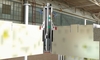
One particular facility comprises a number of settling tanks made up of separate chambers enclosed underneath an operating floor. Fortis Remote Technology has been working to undertake a remote survey of one 25m by 5m chamber using SONAR (sound navigation and ranging) to quantify the settled sludge volume and dispersal patterns. The survey was performed with a SONAR device mounted on a mast lowered into the chamber from a penetration in the floor above.
Previously, single-point SONAR sensors measured the height of the sludge layer immediately beneath the surface of the 3m-deep water, which can be as much as 2.5m high. But this method was slow and relatively inaccurate. Instead, Fortis has developed technology that creates a 3D map of the sediment. To gather map data, Fortis has designed and built a deployment mast that lowers the MEL 2001 SONAR head into the tank by remote control. The mast holds the head steady while it rotates around the vertical axis conducting a 360° scan. Its field of view is 180°. The SONAR head’s transmission frequency is 1 MHz. The measuring head also includes a liquor analyser, which measures pH, turbidity, dissolved oxygen content and temperature. Additional mast sections lower the probe to submerged survey heights of -2600mm, -3700mm and -4278mm below the floor baseplate. (Masts are physically constrained to control azimuth position of SONAR and are of a predefined length). As the detector is submerged, a technician illuminates the sediment immediately underneath the probe to make sure it does not hit bottom. Multiple data collection heights allow the sensor to detect both detail and the shape and depth of indentations in the undulating sediment below. Each scan takes less than an hour.
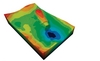
Data is fed to a computer kept away from the chambers to minimise the computer’s exposure. Fortis-designed software creates a closed surface profile from range and bearing information collected by the SONAR unit. The team also calculates the volume of the sediment by measuring the area under the 3D surface profile, taking into account any internal features of the tank.
Across the length and width of the tank, three sampling points were chosen to obtain a complete view of the sediment. These points were specifically chosen to penetrate shadows created by ridges in the sediment, using a perspective view of data based on preliminary site surveys.
The sonar units remain in containment for further scanning at regular intervals. Time series data allows analysis of changes in the sludge dispersal pattern.
| Scanning alternatives |
| Canada-based company AquaCoustic Remote Technologies has partnered with a SONAR device manufacturer to develop a profiling SONAR system with rotating head, the Dual Axis Sonar, primarily for surveying dams and reservoirs. The unit presents sonar profiles on an onboard screen in real-time. Data can be used in 3D imaging software such as AutoCAD. |