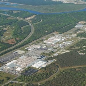
The Loviisa nuclear power plant comprises two 520 MWe VVER-440 reactors located approximately 90 km east of Helsinki at the coast of the Gulf of Finland.
The plant, which is sea-cooled, is currently installing a new emergency air cooling system, which is expected to become operational in 2015.
The system includes two forced-air cooling towers per unit, which will be used for removing decay heat from the reactor and the spent fuel pools and cooling of other equipment critical to nuclear safety.
It will provide cooling in extreme conditions when seawater becomes unavailable for cooling, for instance if there is as an oil catastrophe in the Gulf of Finland, or an exceptional natural phenomenon such as excessive algal bloom.
Fortum, which operates the Loviisa nuclear power plant, says it has studied and developed the new independent cooling system concept for several years. It considered various alternative options,including the use of on-site water storage, a nearby lake and even a plan to dump the heat back into the bedrock, but it says that the air-cooling option offered the only long-term solution for decay heat removal.
The project became a development target following safety assessments carried out by the Finnish Radiation Safety Authority STUK in 2012 as a part of the so-called Post- Fukushima stress tests within the European Union.
The cooling towers are being supplied by the Hungarian firm GEA EGI Contracting/ Engineering Co. Ltd, and are being installed by Caverion, under a EUR 2 million contract. The majority of the installation work will be carried out during normal operations this autumn and winter. This will involve installation of steel frame structures, walls and roof insulations and pipelines. Work to connect the cables to the plant electrical system is being carried out during the annual outage (underway as of mid-August), with around 25-30 people involved in the project. Fortum says that the project is expected to be completed by February 2015, and that the towers will be commissioned next summer.
System design and operation
The cooling towers will be connected to existing systems of Loviisa NPP. One cooling tower is connected to the reserve residual heat removal system (RR) and the other cooling tower is connected to intermediate component cooling system (TF) in each unit (see diagram).
The reserve residual heat removal system removes decay heat generated in the reactor core through the secondary circuit after shutdown of the reactor. Heat is transferred from the reactor core by natural convection to the primary circuit and into the steam generators. The RR system cools the secondary side of the steam generators. A seawater circuit (VF) then transfers the heat to the seawater. If seawater is not available, the RR air cooling tower will provide cooling to RR circuit by replacing the VF connection. Existing pumps of RR systems are utilised when operating the system with cooling towers.
When the reactor is shut down, steam from the steam generators can be vented into the atmosphere before the cooling tower enters operation. During steam venting additional water is fed into the steam generators from a diesel-driven pumping system with dedicated water storage tanks.
The cooling towers are able to provide sufficient cooling capacity in order to bring the plant first into hot shutdown state and later into cold shutdown state with closed- circuit cooling.
The time to achieve shutdown is highly dependent on the weather. As an example, reaching the RR towers’ design capacity (5.8 MW of cooling) with outside temperature of 28.5 degrees would take about three days.
The intermediate component cooling system (TF) cools the fuel pool cooling systems (TG) and other safety-relevant components and systems such as the emergency core cooling system, containment heat removal system, boron injection system and some air-conditioning systems, transferring heat to seawater. If seawater cooling is not available the new TF air cooling tower will provide cooling by replacing the seawater cooling circuit (VF).
The long-term spent fuel storage facility is located in the auxiliary building at unit 2 of the Loviisa nuclear plant and will be cooled by the TF system in that unit.
The external electrical grid or on-site diesel generators can be used to provide electricity for the air cooling system if seawater cooling is lost.
Tower design
The cooling towers themselves consist of finned tube bundles, fans with drive units, connection piping and steel support structures and covers.
The equipment for all four cooling towers will be located in three buildings at Loviisa, each measuring about 10m x 15m x 10m high, that protectthe systems from the elements when they are not in operation.
The buildings will be located on the roofs of Loviisa buildings: the TF towers will each be on top of the tank areas of the relevant units, while the RR towers will be installed above the reserve residual heat removal system (RR) building close to the turbine building for both units.
During cooling operation, tower roofs and side doors are opened to allow air circulation.
The cooling tower buildings will be equipped with electric heating for start-up in winter conditions.
The towers have been designed to remove decay heat generated in the reactor core and also from fuel pools both in the short and long term. The TF cooling tower is dimensioned to remove decay heat from the fuel pool when all fuel from the reactor has been transferred into it for maintenance. It is approximately twice as big as the RR tower.
The seismic classification of the towers is S2; that is, they must withstand the design-basis earthquake without causing damage to safety- classified components.


