Plim & plex
Digging up buried problems
4 March 2011Owners and operators of nuclear power plants are increasingly turning their attention to the issue of the aging of buried pipe at their facilities. By Kathleen Posteraro
Buried pipe includes not only pipe in contact with soil, but also piping that is underground in vaults, culverts and tanks. Underground piping can carry water in many systems, for example fire water, service water, cooling loops, gases, emergency diesel fuel, process water, liquid radwaste and waste water.
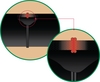
In the past few years, there have been a small but growing number of instances in which various levels of tritium have been reported to have leaked from the underground piping that transports fluids throughout the nuclear station site. While the U.S. Nuclear Regulatory Commission (NRC) has said there has been no threat to public health, reports of tritium leaks from nuclear power plants are a public perception concern and could erode the public’s confidence in the safety of nuclear power plants.
The agency is incorporating concerns about the slow but cumulative degradation of buried pipe into a new version of its Generic Aging Lessons Learned (GALL) report (NUREG-1801) for stations considering extension beyond the initial 40 years of operating life. The first report, published in 2001, had requirements for opportunistic direct inspections of buried piping. The first revision, published in 2005, required inspection of buried pipes once, before entering a lifetime extension period. The second revision, which was published in draft form in May 2010, with a final version expected in early 2011, makes dramatic changes that will have a significant impact on the long-term cost for operation and inspection of buried piping. It will require that all nuclear stations perform multiple direct inspections on metallic piping. It will require greater inspection when degradation is detected. Its expected requirements for process train protection will complicate excavation on site.
Even before the high-profile tritium releases, the industry had begun to respond to the issues with aging buried pipes. In May 2007, the Nuclear Energy Institute (NEI) identified the radiological contamination of soil and groundwater as a top priority through its Groundwater Protection Initiative. Along with commercial plant operators, the Electric Power Research Institute (EPRI) and ASME (formerly the American Society of Mechanical Engineers) began assembling teams of experts to formulate recommendations to help plant engineers prevent and mitigate degradation of buried pipes. Such a proactive approach assesses the piping structural integrity on an ongoing basis rather than reactively responding to leaks.
In November 2009, NEI leaders initiated a buried pipe integrity program with defined steps and schedules; this was recently expanded to include underground vaults (table 1). In accordance with NEI’s timetable, plant operators should have already established in-house roles and responsibilities for the program. By the end of the year, they will complete a risk ranking of underground piping. That includes a mapping of pipe location and layout, as well as documenting the function, material and design of underground piping.
Risk ranking can help plant owners prioritise where to inspect. In 2008, EPRI released the BPWORKS software (product no. 1019178) to conduct risk rankings of buried pipe. The software is based on predictive models of degradation that can be initiated from either the soil side or the fluid side. It uses a points-based model to identify the risk and consequences of breaks, leaks and occlusions that can impede flow.
Operators also need to establish a database to track key program data such as inspection results and trends. Risk ranking will evaluate the likelihood of buried pipe leakage and, considering the hazardous nature of its contents, the consequences of a leak. The resulting risk ranking will be used to prioritize enhanced inspection activities and, if necessary, repair or replacement actions to prevent leakage.
Inspection is a major component of the programme. There are various techniques available, some requiring extensive and costly excavation to get the most data relative to pipe integrity. Data are critical, as they will serve as the basis by which owners will have to make repair/replace decisions, and will define the scope of work and related costs.
However, inspection is challenging. Internal inspection is optimal, but difficult to achieve. The pipes themselves are made of a range of materials: carbon steel, stainless steel and alloys, cast iron, copper alloys, concrete and PVC. They range in size from two inches to more than 10 feet in diameter. Some have external coatings and internal linings; others do not. Some are cathodically protected; others are not. The environment surrounding existing underground piping varies from plant to plant, each with unique chemical, geotechnical and civil-structural considerations. There are perhaps 20 buried pipe corrosion mechanisms.
In many cases mitigation of degraded systems will have to occur during outage windows and will become critical logistical exercises. Outage schedule overruns can result in significant loss of revenue to the utility. Decisions about mitigation need to consider a trade off between long-term performance and the short-term fix. In particular, decisions about whether to repair or replace should include consideration of material selection.
The benefits of HDPE
High-density polyethylene—also known has HDPE—is a promising new material for pipe replacement. Already used successfully in natural gas distribution and municipal water systems, HDPE has been incorporated into safety and non-safety piping systems at some nuclear facilities in the United States and Great Britain. ASME has issued Code Case
N-755 to permit use of HDPE for use in Class 3 safety-related buried piping applications.
A revision to the code case is in progress and is expected to be approved in 2010.
Code Case N-755, Rev. 0 has not been approved by the NRC. However, the commission recently granted two relief requests, allowing HDPE to be used in safety piping at Duke Energy’s Catawba Nuclear Station in South Carolina, and Ameren Corp.’s Callaway Plant in Missouri. Much of the technical content in the relief requests was based on Code Case N-755, Rev. 0. This rule currently limits HDPE to straight pipe, mitred elbows, butt-fused joints and flanged connections for ASME Class 3 applications.
Although not a markedly less expensive material in itself, HDPE is much less expensive to install than carbon steel piping. In addition, it does not corrode and is less susceptible to internal fouling. It can withstand a normal operating temperature range of up to 140°F (60°C) including short-term accident transients up to 176°F (80°C).
Matthew Golliet, a principal engineer of nuclear services at Westinghouse, is a major contributor to ASME nuclear codes and standards activities on the use of HDPE. “Polyethylene is a big saving in both cost and schedule,” Golliet said. “That includes reduced operation and maintenance costs over the life of the plant, including the license renewal term.”
However, direct comparison of material properties between thermoplastics and metal is undesirable due to the variations in application and associated material responses. In particular, successful design with thermoplastics requires recognition of their viscoelastic nature. These materials do not exhibit the relatively simple stress/strain relationship that is characteristic of metals. Duration of loading, as well as temperature and environment, can have a profound effect on their stress-strain response, rupture strength, ultimate strain capacity, and other engineering properties. Mechanical properties vary not only from one class of thermoplastic material to another (for example, between PVC and HDPE) but also within the same generic material, depending on the type and quantity of polymer additives and modifiers, the processing conditions, and the specific nature of the polymer (for example, molecular weight, molecular weight distribution, degree of branching, and extent of copolymerization with other monomers). Long-term characteristic testing is available from the Plastics Pipe Institute (PPI). Ongoing material research and characterization is being conducted through ASME, NRC and EPRI as well as the resin suppliers.
All new nuclear power plant designs are considering the options for HDPE piping applications. HDPE is approved for use in low-temperature, low-pressure ASME B31.1 process fluid applications and other industrial service throughout the balance of plant (BOP). ASME Code Case N-755 has been written for Section III and Section XI applications.
The interest in HDPE system modifications and retrofits has been steadily increasing due to plant concerns and the NEI buried piping integrity programme initiative. Westinghouse is currently responding to this interest. A Westinghouse ‘Customer 1st’ project was developed using input from customers to secure a robust, experienced, and dedicated HDPE supply chain. Westinghouse actively developed ASME requirements for Section III HDPE supplier certificates and is evaluating potential suppliers to these stringent nuclear requirements and is positioned to meet customer needs.
Westinghouse is in a position to qualify its suppliers once, and offer HDPE to the entire industry. “With such a large job as buried piping replacement, a plant operator may have to issue six or 10 contracts, managing each as well as the interactions between those organisations. It takes a lot of time,” Golliet said.
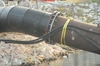
| HDPE butt-fusing |
| HDPE butt-fusing |
| HDPE flanged connections |
| HDPE flanged connections |
| References |
| [1] Handbook of Polyethylene Pipe, 2nd ed, PPI. http://plasticpipe.org/ publications/pe_handbook.html |