Balance of plant: steam handling
Getting bigger
1 October 2012Raising a reactor to 1700 MWe-class as the US-APWR requires new designs for turbine hall condenser and moisture separator reheater. By Issaku Fujita, Teruaki Sakata, Toshiki Kojima, Koichi Inoue, Ryu Suzuki, and Jiro Kasahara
The recent trend in increasing the power generation capacity of pressurized water reactors (PWRs) up to the 1700 MW class for greater economy is met with inherent challenges. Mitsubishi Heavy Industries (MHI) is facing a number of challenges in the design of its 1700 MW class advanced pressurized water reactor for US markets (the US-APWR).
Higher generation capacity necessitates turbines with higher efficiency. Operating the high-pressure (HP) turbine at higher efficiency requires development of a large-sized moisture separator reheater (MSR) to accommodate the higher specific steam volume due to the reduced HP exhaust pressure. The size of condenser tube bundle also increases to the largest in MHI’s experience, to deal with the increased heat rejection rate from the turbine system.
Condenser
In large tube bundle designs, it becomes difficult to ignore condensate sub-cooling and heat transfer deterioration by condensate inundation. Therefore, it is important to reduce the effect of inundation by the optimization of the large tube bundle arrangement. To do this, accurate knowledge of heat transfer, including the behaviour of condensate under gravity field and steam flow, is essential.
Most research on steam condensation on the tube bundle has been conducted for downward steam flow, and research for horizontal steam flow condensation is very limited so far [1-5]. Therefore, it is necessary to clarify the effect of condensate inundation on condensation heat transfer and the condensate behaviour of horizontal steam flow by an experimental approach, especially in the low steam velocity region, where the condensate behaviour is complicated.
With the cooperation of the University of Kitakyushu, MHI has conducted condensation experiments using a horizontal tube bank set up as shown in Figure 1. To investigate high condensate flow in the actual condenser tube bundle, condensate dripping tubes made with stainless sintered metal were used. In order to clarify the effect of condensate inundation on condensation heat transfer in detail, local heat transfer coefficients and condensate flow in the tube bank were measured. By reflecting the experimental result to computational fluid dynamics (CFD) code, MHI built an innovative condenser performance evaluation method.
Experiments
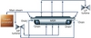
The test loop set-up, shown in Figure 1, is a closed natural-circulation loop of steam and the condensate. The whole loop was thermally insulated with ceramic fibre and was made sufficiently airtight.
Steam was generated in a boiler and flowed through a 90° bend, honeycomb and screen before entering a test section horizontally. The remaining steam from the test section was condensed in an auxiliary condenser containing a copper tube bank and an inlet port to a vacuum pump. Water dripping from the top of the test section was supplied from the boiler by two gear pumps with inverter controllers. Condensate water was exuded through the sintered metal to simulate actual conditions in the large tube bundle.
Results in Figure 2 are interpreted in relation to the Nusselt number, which is a dimensionless heat transfer coefficient:
Nud = hD/?
where h is the condensation heat transfer coefficient, D is the tube outer diameter, ? is the thermal conductivity of condensate as a function of condensate flow rate mdin from the dripping tubes for a range of inlet steam velocity ugap.
As Fig. 2 shows, the Nusselt number decreases with increasing condensate flow rate due to inundation. The Nusselt number rate of decrease is high at low condensate flow rate regions and it falls as the condensate flow rate is increased. It is also interpreted that the degree of heat transfer deterioration by an increase in condensate flow rate is relatively low at the higher condensate flow rate region.
On the other hand, the Nusselt number increases with the steam gap velocity. The increase of heat transfer coefficient with steam velocity is relatively large at the low condensate flow-rate region and it reduces at the higher condensate flow-rate region. The following reasons could be thought as the cause of heat transfer increasing with the steam velocity; (i) the increase of vapour shear force exerting on the condensate film attached to the outer tube surface, (ii) the reduction of heat transfer deterioration at lower tube bank levels due to the decrease in the flow rate of condensate falling from upper tubes because of the increase of condensate flow rate carried downstream in horizontal vapour flow.
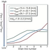
Figure 3 shows an example of the condensate drain distribution by using measuring glass cylinders shown in Figure 1. The vertical axis shows the ratio of condensate flow rate in a drain line mdout to the sum of the condensate supplied from all dripping tubes and the condensate generated on condensing tubes. Since the condensate flow rate from each dripping tube is approximately equal, it is evident that a considerable amount of condensate is carried downstream by horizontal steam flow. As the steam velocity increases, the drain line where condensate flow rate takes the maximum value moves downstream. On the downstream side of the drain line where the condensate flow rate takes the maximum value, the condensate flow rate in each drain line decreases slightly. Under the higher steam velocity conditions, the amount of condensate being carried downstream is quite large, so there is no observable peak.
From the experimental results, we succeeded in developing an innovative condenser performance evaluation method. This method makes it possible to simulate condensate behaviour and heat transfer at the same time with computational fluid dynamics (CFD).
Moisture separator reheater
Operating the HP turbine at higher efficiency requires a higher specific steam volume due to the reduced HP exhaust pressure. Higher specific volume of steam in addition to the increased steam mass flow (kg/hr) in proportion to the uprating of the reactor thermal power also results in higher velocities and increased pressure drops. At higher steam velocity, flow-accelerated corrosion (FAC) is enhanced, and the moisture separator performance will deteriorate due to the increased mist carry-over across the chevron-type vanes.
The development of the MSR for a 1700MW-class PWR involved optimizing the heat balance around the MSR and selecting the optimal size of the MSR for performance and cost. MSR basic design depends on four important parameters: heat transfer, separator performance, pressure drop, and erosion. These parameters were validated for the new MSR design using computational and experimental methods.
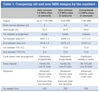
The major design improvements in the new concept of super-sized MSR over the conventional MSR are listed in Table 1. One of the main differences is that in the conventional design the steam chambers for both first and second reheaters are located outside of the shell. Only the steam chamber for the first reheater is inside the shell for in the new US-APWR design.
Table 1: Comparing old and new MSR designs by the numbers
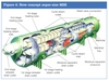
In the new super-sized MSR, shown in Figure 4, three cycle steam inlet nozzles are distributed longitudinally to ensure decreased steam velocity to protect the shell plate from FAC, and to provide uniform static pressure distribution in the vessel longitudinal direction for better mist separation performance of the separator vanes.
Cycle steam entering through the inlet nozzles hits the impingement plates, turns along them and then flows longitudinally along the manifold. Cycle steam is then distributed to the assembly of advanced separator vanes through the slots along the manifold. After passing through the separator vanes, the steam again turns upwards, flows across the tube bundles and finally exits through the outlets at the top.
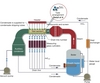
Wet exhaust steam from the high-pressure turbine is regenerated by the moisture separator and reheated by the reheater bundles before entering the low-pressure (LP) turbine. The MSR contains two stages of reheat: using extraction steam from the HP turbine as the heating steam for the first stage reheater, and using main steam from the steam generator as the heating steam for the second-stage reheater.
The schematic arrangement of the MSR is shown in Figure 5. The steam passing through the MSR shell is also called the cycle steam and that in the MSR tube is called heating steam.
Optimization
The design of the APWR up to 1700 MW-class required optimization of the heat cycle for maximizing the efficiency of the turbines. The reheat steam pressure is reduced from 1.2 MPa to 1.0 MPa for an improved heat cycle, thereby increasing the specific volume of reheat steam. To compensate for the increased pressure drop, decreased performance of the moisture separator, and increased internal shell erosion due to the higher specific volume of steam, it was essential to scale up the moisture separator reheater also.
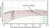
The MSR performance was optimized for the terminal temperature difference (TTD) of the first and second stages. TTD is defined as the difference between the heating steam saturation temperature at reheater inlet and the cycle steam outlet temperature. From the optimization of heat load on MSR, the optimum setting of TTDs is found to be 16.7°C for the first stage and 8.3°C for second stage for a new super-size MSR. This compares to a TTD of 13.9°C for first and second stages for conventional MSRs. The reheater TTD for different vessel diameters is plotted in Figure 6.
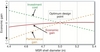
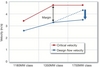
An economic evaluation of the size of the MSR shell diameter, as shown in Figure 7, was conducted considering the trade-off between economic gain due to the improved performance and increased fabrication costs for larger-size MSRs.
Based on the study, an optimum vessel diameter of 5.0 m was selected within the limitations imposed by the available shop capacity for fabrication. To accommodate the tube bundles, space between the first and second stage steam chamber is eliminated and the first stage steam chamber is contained in a pressure vessel.
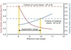
Next, for a MSR vessel diameter of 5.0 m, the effective tube length is optimized as shown in Figure 8. It should be noted that longer tubes have better heat transfer capability and lower cycle steam pressure drop, but the heating steam pressure drop through the tubes increases. Cycle efficiency depends more on cycle steam pressure drop than heating steam pressure drop. Hence, an effective tube length of 10 m is selected for which the cycle steam pressure drop is minimal in the available design application space of 8 ~ 10 m.
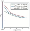
At a higher specific steam volume, conventional chevron-type vanes would encounter significantly higher steam velocity at their inlet, thereby reducing the available velocity margin as shown in Figure 9. To maintain the same margin between the design velocity and critical velocity as in conventional units, the effective length of chevron vanes has increased to 1280 mm from 1050 mm. However, only chevron vanes up to an effective length of 1050 mm have been verified so far and used in conventional MSRs.
Toshiki Kojima (toshiki_kojima@mhi.co.jp), Issaku Fujita, Jiro Kasahara, Ryu Suzuki and Teruaki Sakata are with Mitsubishi Heavy Industries Ltd. Main contact: Toshiki Kojima, Mitsubishi Heavy Industries, Ltd., Kobe Shipyard & Machinery Works, 1-1, Wadamisaki-Cho 1-Chome, Hygo-Ku, Kobe 652-8585, Japan. Koichi Inoue is with The University of Kitakyushu, Japan. Parts of this paper are based on ICONE 20-POWE2012-54175 from the 20th International Conference on Nuclear Engineering, 30 July-3 August, Anaheim, California, USA; and ICONE 18-29157, 19-21 May 2010, Xi’an, China.
This article was published in the September 2012 issue of Nuclear Engineering International.
References
[1] Fujii, T., Uehara, H., Hirata, K. and Oda, K., 1972, "Heat Transfer and Flow Resistance in Condensation of Low Pressure Steam Flowing through Tube Banks", Int. J. Heat Mass Transfer, vol.15, pp.247-260.
[2] Kutateladze, S. S., Gogonin, I. I., Sasounov, V. I., 1985, "The influence of condensation flow rate on heat transfer in film condensation of stationary vapour on horizontal tube banks", Int. J. Heat Mass Transfer, pp.1011-1018.
[3] Honda, H, Uchima, B., Nozu, S., Nakata, H. and Fujii, T., 1988, "Condensation of downward flowing R-113 vapor on bundles of horizontal smooth tubes", Trans JSME(B) vol.54, no.502, pp. 1453-1460 (in Japanese).
[4] McNeil, D. A., Cuthbertson, G. and Burnside, B. M., 2001, "Experimental Study of Low-pressure Filmwise Condensation on a Small In-line Tube", Proc. Instn. Mech. Engnrs., vol.215, Part A, pp. 231-243.
[5] Randall, D. L. and Eckels, S. J., 2005, "Effect of inundation upon the condensation heat transfer performance of R-134a: Part II - Results", HVAC & R Research, Vol.11, no.4, pp.543-562.
Moisture separator reheater
[1] Manabe, J., Kasahara, J., Moisture Separator Reheater for NPP Turbines, Journal of Power and Energy Systems Vol. 3 No. 2, pp 368-381.
[2] Nakagami, Y., Yoshioka, T., Sasaki, T., Manabe, J., Matsukuma, M., Taniguchi, M., Miyawaki, T., Design and Field Operation of Advanced 900 MW class PWR Turbine Plant (in Japanese), Mitsubishi Jyuko Giho, 1985, Vol. 22, No. 3
[3] Nakagami, Y., Manabe, J., Urabe, T., Nakahara, T., Kawaguchi, S., Design and Operation of Moisture Separator Reheater for Nuclear Steam Turbine System (in Japanese), The Thermal and Nuclear Power, 1982, Vol. 34, No.2, pp. 185-198.
[4] Fujita, I., Machii, K., Sakata, T., Development of High Performance Moisture Separator Reheater, Proceedings of Power 2009, 81092, ASME Power 2009, July 21-23, Albuquerque, Nex Mexico, USA.


