Fast reactor focus: India
Great expectations
8 January 2010India’s prototype fast breeder reactor, due to go critical next year, paves the way for the country’s ambitious plans for nuclear energy. By Baldev Raj, S.C. Chetal and P. Chellapandi
A fast neutron spectrum reactor has the flexibility to operate as breeder to achieve net creation of transuranics, as convertor to balance the transuranic production and consumption and as transmuter to convert the long lived minor actinides and other radioisotopes to short lived ones. These features enable uranium to be used 60 times more efficiently, reduce the toxicity of high-level waste and time it takes for the waste to reach natural radiation levels. Therefore, several fast reactors have been built and operated worldwide, accumulating about 390 reactor-years of operating experience to date.
Fast breeder reactors (FBR) will be essential if India is to achieve its target of a 25% (300GW) nuclear share by 2050, given its limited uranium resources. FBRs will play a role in the second phase of India’s Three Stage Nuclear Power Programme, formulated by Dr. Homi Bhabha. Stage one involves the deployment of natural uranium pressurized heavy water reactors. It will be followed by concurrent deployment of FBRs burning plutonium to breed U-233 from thorium. The FBRs will be followed, in the third stage, by Advanced Heavy Water Reactors (AHWRs) capable of utilizing India’s abundant thorium resources.
India started its FBR programme by constructing an experimental loop type fast breeder test reactor (FBTR) at Kalpakkam. FBTR is a sodium cooled 40MWt/13.2MWe reactor and was commissioned in 1985 with an unique plutonium rich carbide fuel. FBTR was followed by the design and development of 500MWe capacity Prototype Fast Breeder Reactor (PFBR), currently under construction.
The main objective of PFBR is to demonstrate the techno-economic viability of sodium-cooled fast reactors for commercial deployment. In addition, it will provide a demonstration of comprehensive closed fuel cycle technologies such as fuel fabrication, reprocessing, waste management and waste immobilisation. PFBR will enable validation of first-of-a-kind design concepts and the experience gained during operation and maintenance of mechanisms, components and sensors in the sodium environment and at reactor operating temperatures (820K) will lead to standardisation for the adoption in the series of future reactors.
Through continuous focused and innovative R&D, we shall generate confidence for the introduction of higher performance parameters such as enhanced burnup (200GWd/t), operating temperature (increase by 20K), design life (increase by 20 years), and increase in load factor (15%). Indian industries involved in the manufacture of large-dimensioned components with tight specifications also stand to gain from increased human resource capacity and capability for the design, construction and operation of a series of commercial reactors and associated fuel cycle facilities.
The design and development activities for PFBR were carried out at Indira Gandhi Centre for Atomic Research (IGCAR), Kalpakkam, a mission oriented centre dedicated to R&D on fast reactor technology. Bharatiya Nabhikiya Vidyut Nigam Limited (BHAVINI), a government company formed in 2003 is implementing the project. The reactor construction was started in 2003 and is scheduled to be commissioned by 2011.
Main concepts
The strategy is to develop robust, safe and economical sodium-cooled fast reactors in the country. The choice of sodium is based on the vast national and international experiences derived from the operation of many experimental loops, test and prototype reactors. The plant capacity of 500 MWe is based on the maximum fossil power plant capacities successfully installed at that time of initiation of conceptual design phase in India. More than thirty 500 MWe capacity thermal power stations are currently operating in the country. Based on international and national experience, the mixed oxide fuel with natural uranium and approximately 30% Pu oxide was chosen. In the Indian context, complete experience is available through indigenous PHWR program for oxide fuel and MOX fuel in BWRs. The operating temperature of 820K with 40 years design life were selected based on extensive investigations on structural mechanics (creep-fatigue damage in welds is the major life-limiting factor), economics, operating experiences and current international trends. With the current knowledge, operating experience, particularly with Russian BN-type reactors and state of art O&M strategies, a load factor of 75% has been chosen. We are likely to achieve better load factors with continued experience and feedback.
Pool- and loop-type concepts were studied comprehensively considering the associated merits and demerits specific to medium-size reactors like PFBR. It was concluded that the pool type would be our choice. The governing parameters meriting the choice are large thermal inertia that permits high thermal shock, higher structural reliability due to lesser number of critical welds associated and compact layout of primary circuit components. It is also our perception that the complexities that are associated with the pool type of reactor such as pool hydraulics, manufacturing and handing of over-dimensioned thin vessels with stringent tolerances can be successfully met by the designers and our industry. Subsequently, it has been confirmed from detailed analysis backed up with experimental validation and an extensive 1:1 technology development exercise.
The strategy of selecting the minimum number of systems, components and materials possible has been adopted in-line with the international trends for innovative reactors. A two-loop concept with two primary pumps, two intermediate heat exchangers per loop and two secondary sodium pumps was selected, after considering comprehensively the associated parameters such as economics, plant availability, size and number of components, operating experiences and capacity and capability of Indian industries and safety aspects. Regarding structural materials, 20% cold worked austenitic stainless steel (15Cr-15Ni-Mo-Ti stabilised called ‘D9’) was chosen for the claddings and wrappers. For the components and pipings operating in sodium, SS 316 LN for high temperatures and SS 304 LN for colder temperatures are chosen. For the steam generator modules, ferritic steel, modified 9Cr-1Mo is employed. For the top shield of the reactor assembly, which is a box type structure, carbon steel with controlled phosphorus and sulphur (A48P2) has been chosen to avoid laminar tearing problems.
A higher burnup is desired for achieving economy through reduction in the fuel cycle cost and the reduction is particularly significant for FBR (40% to 60% of fuel cycle cost when burnup increases from 100 GWd/t to 150 GWd/t with further incentives for higher burnups). This is in contrast to PWR for which the reduction tends to saturate at about 20% for a burnup of about 80 GWd/t. However, with the current structural materials for the clad and hexagonal wrapped, burnup is targeted to maximum 100 GWd/t in the initial phase.
Description
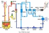
The overall flow diagram comprising primary circuit housed in reactor assembly, secondary sodium circuit and balance of plant (BoP) is shown below.

The nuclear heat generated in the core is removed by circulating sodium from cold pool at 670 K to the hot pool at 820 K. The sodium from the hot pool mixes with the cold pool after transporting its heat to four intermediate heat exchangers (IHX). The circulation of sodium from the cold pool to the hot pool is maintained by two primary sodium pumps and the flow of sodium through the IHX is driven by a level difference (1.5m of sodium) between the hot and cold pools. The heat from IHX is in turn transported to eight steam generators (SG) by sodium flowing in the secondary circuit. Steam produced in SG is supplied to turbo-generator.
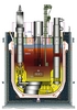
In the reactor assembly, the main vessel houses the entire primary sodium circuit including core. The sodium is filled in the main vessel with free surfaces blanketed by argon. The inner vessel separates the hot and cold sodium pools. The reactor core consists of about 1758 subassemblies including 181 fuel subassemblies. The control plug, positioned just above the core, mainly houses 12 absorber rod drive mechanisms. The top shield supports the primary sodium pumps, IHX, control plug and fuel handling systems.

Design challenges
The possible failure modes are identified by systematic analysis of literature and our own perceptions and analysed in detail employing validated analytical, numerical and experimental techniques. A few challenging issues addressed in the design are: high temperature design for long reliable operation of components operating at temperatures around 820 K for a design life of 40 years, design of mechanisms and rotating equipment operating in sodium and argon cover gas space, handling the sodium leaks and sodium water reactions in the steam generators, seismic analysis of interconnected buildings resting on a common base raft, seismic design of thin walled vessels, pumps and absorber rod mechanisms, and in-service inspection (ISI) of reactor internals within sodium. High neutron flux causes high material damage due to irradiation, compared to thermal neutron reactors. Sodium, because of its opaqueness, poses problems for ISI. A sodium leak is also of concern for operation and maintenance. However, low operating pressure offers advantages over thermal neutron reactors in terms structural integrity. These issues have been resolved successfully by the extensive analysis, testing and evaluations with the mission mode approach.
Mechanisms such as shutdown and fuel handling (transfer arm) systems operating in sodium at high temperatures were qualified with full-scale tests.
Regarding the safety features of PFBR, it possesses all the intrinsic safety features specific to fast reactors. Sodium components with safety significance (all sodium components of the reactor assembly) are designed as per RCC-MR-2002, the French design code specific to FBR. For the aspects not covered in the design codes, such as structural design criteria for irradiated core components, thermal striping, effects of sodium, and high strain rate loadings, interim rules have been established based on literature and extensive data generated in-house and approved by Atomic Energy Regulatory Board-appointed committees of experts. All the probable internal and external events are identified, categorized into Design Basis Events (DBE) and Beyond Design Basis Events (BDBE) and analyzed using validated and approved computer codes. Core disruptive accidents, considered as BDBE, are analysed in detail using a dedicated computer code called FUSTIN, which simulates several complex phenomena involved in determining the transient pressures, vessel displacements and strains. It was developed and validated thoroughly by solving relevant benchmark problems.
Using this code, the transient responses of the PFBR’s main vessel are determined. In order to have good understanding of the complicated loading mechanisms and sequences, the effects of introduction of internals in the main vessel were analysed. To demonstrate the structural integrity of the heat exchangers that are important for decay heat removal after an accident, a 1/13th-scale mock-up was conceived. Tests were conducted by developing and characterizing suitable low density explosives to simulate nuclear energy release characteristics. The tests have indicated relatively lesser displacements and similar strains in the vessel compared to numerical predictions. The structural integrity of decay heat exchangers were demonstrated. Thus the reactor assembly meets the safety criteria specified for PFBR. Another important result of the study is that the amount of sodium expelled into the reactor’s containment building (RCB) from the hot sodium pool, through top shield penetrations, subsequent to sodium slug impact. The pressure rise due to consequent sodium fire in the RCB forms the basis for establishing design pressure of 25 kPa for RCB.
Construction status
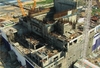
The nuclear island, which houses a total of 17 buildings, including safety-related structures, is under construction. Eight buildings make up the single nuclear island connected buildings structure, namely the reactor containment building, two steam generator buildings, two electrical buildings, control building, radwaste building and fuel building are connected together as a single structure. The NICB is supported on a common raft foundation which covers an area of approximately 102m by 93m. The reactor vault construction has been successfully completed, meeting the stringent dimensional tolerances required for the specified erection tolerances. The excavation works for the balance of plant (BOP) has been completed.
The nuclear steam supply system components have been manufactured by the Indian industries, based on the experience gained through technology development and including feedback from in-sodium testing. Manufacture of large components like the safety vessel, main vessel, inner vessel and thermal baffles are completed, meeting stringent tolerance requirements. The safety vessel, incorporated with delicate thermal insulation panels, was the first major nuclear equipment to be erected successfully in June 2008.
As the manufacturing tolerances are very crucial for meeting the functional and structural integrity considerations, tight values have been specified. Form tolerances less than the half of the wall thickness have been achieved consistently for all the large components. This achievement is possible due to the extensive manufacturing development work completed as a pre-project activity as well as coordinated efforts of task forces involving IGCAR and BHAVINI constituted for these purposes. Elegant methodology has been finalized for the subsequent erection of main vessel along with internals and top shield, respecting various erection tolerances giving due considerations to time and economy. In addition, sodium has been transferred safely to storage tanks.
Fuel cycle
Though the fast reactor fuel reprocessing programme has gained from domestic thermal reactor fuel reprocessing, special features of the reprocessing of fast reactor fuels with high plutonium content, high burn-up and low cooling time have been identified and addressed through an R&D programme. To reprocess the fuel discharged from FBTR, a small scale reprocessing facility (CORAL) has been set up at IGCAR. Fuel discharged from FBTR up to a burn-up of 150 GWd/t has been successfully reprocessed in this facility. This experience has provided necessary inputs for completing the Demonstration Fuel Reprocessing Plant (DFRP), which would be commissioned by the year 2010. The fuel discharged from PFBR in the initial stages is proposed to be reprocessed in the DFRP, which is designed to handle carbide as well as the oxide fuel in the head and steps. However, a dedicated commercial scale reprocessing plant is proposed to be constructed as part of the Fast Reactor Fuel Cycle Facility (FRFCF) that will be co-located with the PFBR. This will include a fuel fabrication plant, a reprocessing plant, assembly plants and a waste management facility.
Beyond PFBR
It is planned to construct six 500 MWe commercial fast breeder reactors (CFBR), similar to PFBR with improved economy and safety, during 2013-20. In the CFBR, MOX fuel and the two-loop concept would be retained. To improve economy, other features under consideration include: a twin-unit concept, optimum shielding, use of 304 LN in place of 316 LN for cold pool components and piping, 85% load factor, 60 years design life, reduced construction time (5 years) and enhanced burn up (up to 200 GWd/t, to be achieved in stages), and three SG modules per loop with increased tube length of 30m (for comparison, PFBR has four 23m-long modules per loop).
It has been realized that for enhanced growth of fast reactors in the country, it is imperative to develop metallic-fuelled FBRs, which promise a much higher breeding. A comprehensive programme on development of a metal-fuelled reactor and its fuel cycle has been undertaken with the aim of introducing metal fuel in commercial FBRs of 1000 MWe capacity beyond 2020. Fabrication of test fuels for irradiation in FBTR and a pilot plant for pyrochemical reprocessing are planned. Research has begun at the Department of Atomic Energy to develop metallic fuels for achieving a high breeding ratio (1.45) and high burnup of ~ 25 at %.
Author Info:
Baldev Raj, S.C.Chetal and P. Chellapandi, all of the Indira Gandhi Centre for Atomic Research, Kalpakkam-603 102, India. The science and technology contributions by the team of scientists and engineers from IGCAR, BHAVINI, collaborating institutes and Industries are sincerely acknowledged.
Related ArticlesTaking stock of India L&T put the roof on Millimetre matters Prototype reactor to start construction India's PFBR vessel installed| References & Reading List |
| 1] Baldev Raj, 'Status of Sodium Cooled Fast Reactors with Closed Fuel Cycle in India', 2007, International Congress on Advances in Nuclear Power Plants, Nice, France, May 13-18, 2007. |