Inspection
Reaching into the depths of steam turbines
22 July 2004Robotic manipulators can be used to reach inside large power equipment of various kinds to perform inspections without costly and time-consuming disassembly. More utilities are using robotic inspection tooling to perform quick condition assessments during brief downtimes, and using this information to plan parts procurements and repairs.
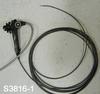
Detailed diagnostics and condition assessments on large steam turbines are often performed using remote visual inspection equipment. Figure 1 shows a common videoscope used for a variety of plant inspections. These products are designed as one-size-fits-all tools which can be used to inspect everything from turbines to piping to piston engines.
While these products perform well in many cases, their main drawback is their inability to access all areas of a steam turbine that might be required to evaluate a particular problem. In particular, their extreme flexibility becomes a liability when a problem is in the mid-span stages of the turbine, or in areas requiring the crossing of large, unsupported gaps from the access point to the inspection target area.
In these cases, tooling designed specifically for the problems faced during steam turbine inspections is required. Such tooling requires a combination of stiffness and flexibility and a degree of self-support that typical videoscopes lack. New inspection tooling would also require the ability to be easily reconfigured to respond to the large differences between steam turbine configurations (in contrast to, say, gas turbines, which tend to be very similar to one another, steam turbines come in a large variety of configurations and each unit presents almost unique inspection challenges).
Through work with the Electric Power Research Institute – which had originally collaborated with Foster-Miller to create the CECIL system (for inspection and cleaning of steam generators on PWRs) – Foster-Miller developed a series of robotic manipulators to deliver visual inspection capability deep into large power plant steam turbines.
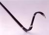
Figure 2 shows an example of such tooling as developed through work with naval steam turbines.
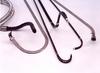
The primary differences between this group of tools and conventional off-the-shelf videoscopes are: their axial stiffness, the increased number of degrees of freedom, and their ability to support themselves (see Figure 3).
A CASE OF HIGH VIBRATION
The following is a description of work performed at a utility plant in the mid-western USA. The unit was a 321MWe Westinghouse cross compound steam turbine generator that has been in service since 1961. The turbine consisted of four sections: a high pressure and intermediate pressure section on one shaft driving a full speed (3600rpm) generator, and two low pressure turbines (LP-1 and LP-2) driving a half-speed (1800rpm) generator. Each low pressure turbine section consisted of 13 stages, with 44-inch (112cm) long last stage blades. This fossil steam turbine design later evolved into a double flow design (BB 81) used in many nuclear power plants.
As with most utility steam turbines, shaft vibration is continuously monitored on this unit with alarms and automatic trips at pre-set levels. Bearing oil is routinely sampled on a weekly or monthly basis. Input and output steam conditions are also monitored. The current inspection was triggered by increased vibration in the LP-1 section of the turbine.
The LP-1 turbine section was overhauled previously in 1997. Approximately six months after the overhaul, the turbine could not be restarted due to high vibration following a short shutdown. Due to operational constraints, it was decided to trim balance the rotor until a more convenient time was reached to perform a detailed diagnosis and correct the problem.
At that time, a total of 10 lbs (4.5kg) of balance weight was added to the turbine to facilitate operation within normal vibration limits. The 10 lbs of weight was far in excess of the normal 1-2 lbs to conduct in-service trim balancing. There was no other external indication of problems, such as a measurable decrease in output or steam conditions. The turbine continued operations while further steps for investigation were decided upon. Since the vibration problem did not continue to worsen, neither further diagnosis nor disassembly and repair were financially called for.
Detailed diagnostics
While the unit operated for several years after the initial vibration problem was discovered and field-corrected, it was still known that the rotor had sustained serious damage. What was not known was the exact nature and extent of the damage. Without that information, it would be difficult for the operator to economically plan any repair work that would correct the problem. If the unit’s casing was removed, for example, it was unknown what spare parts would be required to make repairs. Typically, turbine blades over 12 inches (30cm) in length are made from forgings requiring a manufacturing lead time of 12-16 weeks. This makes it economically unsound to open the casing for a planned 6-10 week overhaul without already having ready replacement blades. This machine is the only one of this design operated by the owner, although about six similar machines are operated by other companies. With an expected life of the blades of over 40 years, buying ‘insurance’ or ‘warehouse’ spares is not economic either.
In this case, the unit had operated for over four years after the initial incident without further indications of problems. The rationale for doing further inspection was not therefore a fear of further equipment failure or to determine a risk of failure, though that was a benefit as well. The main purpose of further inspection was to determine prior to opening the casing what repair work would be needed and to stock the necessary spares well in advance. From a business process point of view, the aim is to plan, schedule, man, and budget for pre-planned work and minimise the emergent work.
Conventional inspection
During a short outage in August 2002, a conventional videoscope was used in an attempt to find the source of the rotor imbalance. The inspection was performed from inside of the condenser, inserting the videoscope through the bottom of the flow guide. The scope was inserted through the exhaust end of the LP-1 turbine starting with the L-0 buckets and was pushed through as many blade rows as possible. In the event, it was only possible to penetrate the unit to the L-1 rotating stage with the conventional scope.
In this kind of situation, attempting to penetrate blade rows with this kind of tool is like ‘pushing a rope’. Since the tool has no axial stiffness, it is impossible to push forward when navigating the large changes in angle (90º or more in some cases) from rotating to stationary blades. It was only possible to penetrate two blade rows into the unit, and no problems were found. The unit was put back into service and the utility continued to monitor.
Inspection with improved tooling
During another planned outage in May of 2003, improved tooling was used in an attempt to find the source of the rotor imbalance in the unit. This brief outage came about four months prior to a planned overhaul of the unit. Thus, there was still time to use the results of the inspection, if successful, to plan repair work and procure any spare blading required.
Due to its stiffness in the axial direction, a bi-directional articulated tool (shown in Figure 4) was chosen that could steer into the mid-span stages of the turbine. The tool was able to navigate past 9-10 blade rows into the L-3 to L-4 stages. An illustration of the difference in reach of the two tools can be seen in Figure 5.
The key find of the inspection was a missing shroud band segment on a rotating stage. Figure 6 shows a comparison of the missing shroud band to an intact shroud band. Figure 7 shows the break in the shroud band more clearly.
Due to this missing band, the other bands on the stage showed signs of buckling and damage (Figure 8). Surprisingly, damage to downstream nozzles and buckets due to the loss of this material was minimal and in general the unit showed erosion at levels expected given its time in service.
After the initial corrective balancing in 1997, the machine operated normally until September 2003, when it was overhauled. After the second inspection revealed the missing shroud sections, continuing to operate the machine was a risk assessment based on knowledge of turbine blades and failure mechanisms as well as an understanding of the seasonal nature of the power generation business. Past experience suggested that if there was a mistuned blade, it would have failed long ago, typically within weeks or months of continued service. Additionally, there is always a risk of further damage induced by the debris from the initial failure. Since the unit had operated for at least four years since the initial failure, there was a high degree of confidence that the blades would last until the planned overhaul shutdown.
The pictures from the remote inspection persuaded company management that a replacement L-3 blade row should be ordered from the manufacturer in advance of the overhaul. The advance inspection allowed the blades to be ordered with the ‘normal’ lead-time, enabling the blade shop to manufacture them in the off-peak season and avoid overtime, at a lower price than emergency delivery. Thus replacement L-3 rotating blades were on hand at the start of the overhaul.
Maintenance action
The casing was opened on schedule in September of 2003, the damage was found to be more extensive than had been seen with the remote inspection. Blades were damaged on three rows, not solely the one row previously identified. The L-3 blade row whose replacements had been ordered as a result of the inspection had extensive damage, including missing shroud, bending, nicks, and dings in the airfoil section due to debris from other failures of previous stages. Two other stages had also suffered shroud failures which were repaired by conventional weld restoration of the blade tenons and re-attachment of the new shroud.
Shrouding on turbine blades is provided to control vibration and the resulting cyclic stress level in the blades, as well as provide a sealing surface to minimise steam leakage around the blade. The shroud failures were determined to result from improper installation of the alignment load blocks for the stationary blade rings during the previous re-assembly. The improper installation squeezed the blade rings at the horizontal centreline and initiated rubs and eventual shroud failures.
Due to the additional damage and repairs needed, the duration of the outage was increased approximately two weeks from the original plan. Having replacement L-3 blades on hand at the start of the overhaul probably reduced the duration by five weeks or more, for a savings of millions of dollars in electric power generation.